
Base build

Base build testingLB500LB600LB700ACLB 200Standard or solid-state switching

End-of-line

End-of-line testingLCLB 160LCLB 240ACLB 60

Applications

Cooling

Chillers and cooling plantStatic and dynamic load testing

Power

UPS systemsGeneratorsSwitchgear and power qualityProtection settings

Explained

Liquid coolingGPU load testingWater qualityLoop monitoringCommissioning

Equipment

Commissioning equipment

Manifold trolleyFlushing & refill cart

Tools

The full rangeSizing calculatorDatasheets

Services

Commissioning supportLoad bank hireHigh load simulationBespoke load banksSupply and installationMaintenance and repairDeployment and managementBuy or hireProjects

Company

AboutPartnersProjectsAcademyNewsEventsFAQ Speak to the team
High load simulation

High load simulation for AI data halls

AI changed the behaviour of the load, not just its size. Solid-state switching lets the load bank follow it, so the hall is tested against that behaviour before it goes live.

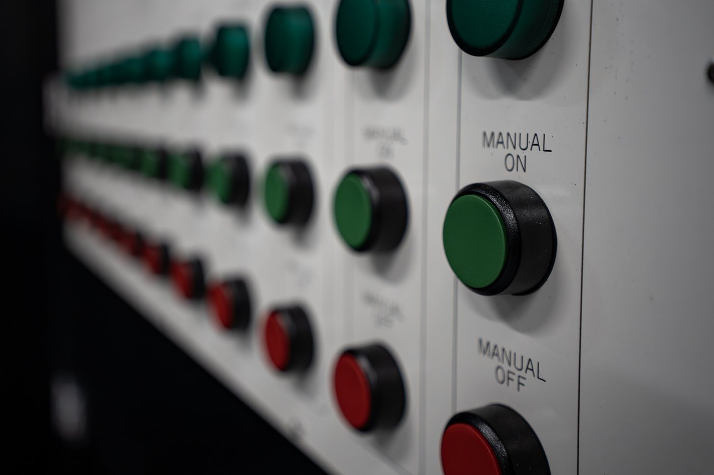
Load step controls on a PowerLoad unit: each step switched individually up to full load
RackLevel, not just the riser
Solid stateFast load stepping
RepeatableStored load profiles
LoggedFlow, temperature, pressure

High load simulation tests a data hall with a load that behaves like the equipment that will occupy it. Solid-state switching follows the fast load changes of an AI rack, and the end-of-line range applies them at each rack position, so switchgear, generators, UPS and the cooling loop are tested against how the hall will behave.

Steady load and GPU load

The grey line is what a conventional load bank asks of a hall. The orange line is what a rack of GPUs asks.

Conventional load bank PowerLoad solid-state switching
What it catches

Problems that only appear under a moving load

Each of these can hide behind a steady load bank.

At the switchgear

Protection settings that read a fast swing as a fault and open a healthy circuit.

At the generators

Sets that carry the rating comfortably but cannot follow the rate the load arrives at.

At the UPS

Strings that hold one step cleanly and degrade over repeated ones.

At the CDU

A loop that keeps up with average heat and falls behind the peaks.

At the rack

Busway and tap-off behaviour that a riser test does not show.

Across the hall

Interactions between plant that only appear when everything moves at once.

What we simulate

Profiles that match the hall you are building

The profile is set to the equipment going in, not to whatever the load bank can do.

  • Fast step changes between near idle and full draw
  • Sustained peak to prove thermal capacity, not just electrical
  • Ramps at the rate the racks will actually ramp
  • Repeated cycling to find the components that drift under it
  • Rack-level heat and electrical load with the end-of-line range
  • Partial-load conditions as well as peaks
  • Steady heat load for base build testing
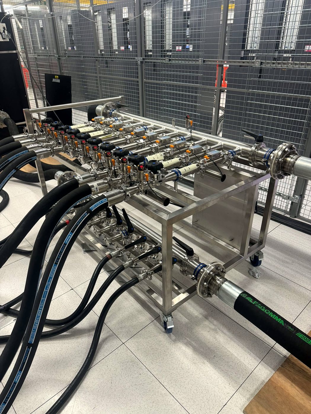
A PowerLoad manifold rig connected in a live data hall
Where halls fail

Most failures are about the rate of change, not the peak

A hall that carries its rating can still drop when the load moves quickly. Protection reads a fast swing as a fault, generators cannot follow the ramp, and the loop cannot shed heat as fast as it arrives. None of it shows up under a steady load.

  • Switchgear and protection that trips on a transient it reads as a fault
  • Generator sets that cannot follow the ramp rate
  • UPS strings taking repeated steps they were never proven against
  • Coolant loops that lag the heat rather than track it
See the six failure modes
FAQ

High load simulation, answered

High load simulation tests a data hall with a load that behaves like the equipment that will occupy it, rather than a steady resistive draw. For an AI hall that means reproducing the swings a rack of GPUs creates, so the switchgear, generators, UPS and cooling are proven against real behaviour.
A steady load proves a hall can carry a number. It does not show whether the hall can handle the rate of change. AI racks move between near idle and full draw far faster than traditional IT load, and many failures come from that rate of change rather than the peak.
With solid-state switching, which steps the load far faster than contactor-based banks. It is optional on the LB500 and LB600, built into the LB700 and the LCLB GPU emulators, and lets the load bank follow a profile rather than a staircase. Profiles can be set before you arrive and repeated identically for comparison.
Yes. That is end-of-line testing with the LCLB 160 and LCLB 240: true rack-level heat and electrical replication at each rack position, so the busway, tap-off, local protection and cooling are tested at the point the GPUs will sit.
Yes. Profiles are stored and replayed, so hall two is tested against the same shape as hall one and the results are genuinely comparable rather than being a matter of who ran the test.
Yes. Base build testing with the LB500, LB600, LB700 and ACLB 200 proves the cooling plant has the capacity while the hall is built. Solid-state switching is an optional extra where the specification asks for transient testing. End-of-line testing with the LCLB 160, LCLB 240 and ACLB 60 then replicates the live rack.
Yes. The system has to respond in both directions. A hall spends most of its life below peak, and switchgear, generators and cooling can behave just as unpredictably stepping down as stepping up. PowerLoad units step down as well as up, so partial-load conditions are tested rather than assumed safe.
Related

Where this leads

Test the hall against its real behaviour

Tell us the IT load and the equipment going in. We will build the profile around it.