Base build

Base build testingLB500LB600LB700ACLB 200Standard or solid-state switching

End-of-line

End-of-line testingLCLB 160LCLB 240ACLB 60

Applications

Cooling

Chillers and cooling plantStatic and dynamic load testing

Power

UPS systemsGeneratorsSwitchgear and power qualityProtection settings

Explained

Liquid coolingGPU load testingWater qualityLoop monitoringCommissioning

Equipment

Commissioning equipment

Manifold trolleyFlushing & refill cart

Tools

The full rangeSizing calculatorDatasheets

Services

Commissioning supportLoad bank hireHigh load simulationBespoke load banksSupply and installationMaintenance and repairDeployment and managementBuy or hireProjects

Company

AboutPartnersProjectsAcademyNewsEventsFAQ Speak to the team
Visibility inside the loop

What does each outlet on the manifold trolley do?

Every outlet metered on its own, so no circuit hides in the average.

Published 26 August 2026

0:25
Manifold outlet specification
MeteredEvery outlet, on its own
LiveFlow, temperature, pressure
SetTarget pressure drop per valve
OneConnection to the secondary loop

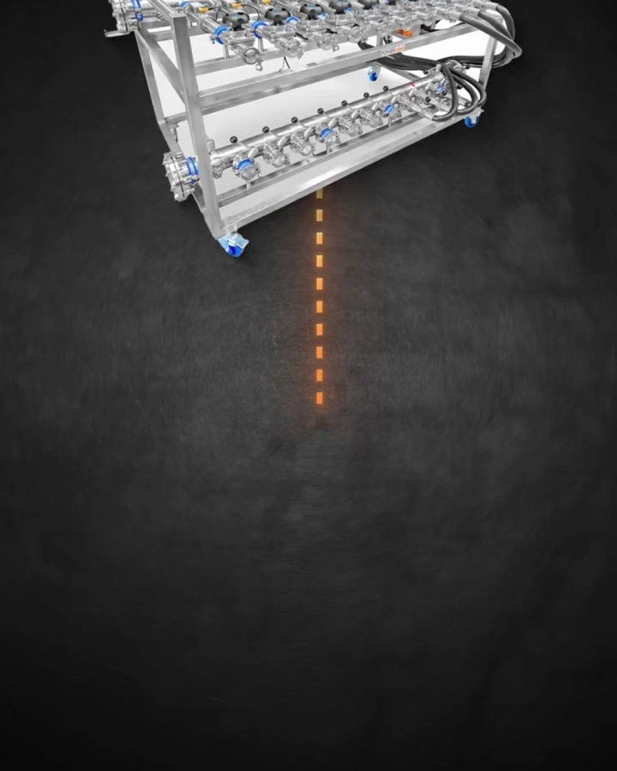
The manifold trolley runs 1 to 2 inch hose pairs from a single connection to the secondary fluid network. Each outlet has an electronic flow meter reporting live flow rate and temperature to the controller, and a target pressure drop can be set on each valve. Every rack is fed and measured on its own.

The full answer

Many hose pairs from one network

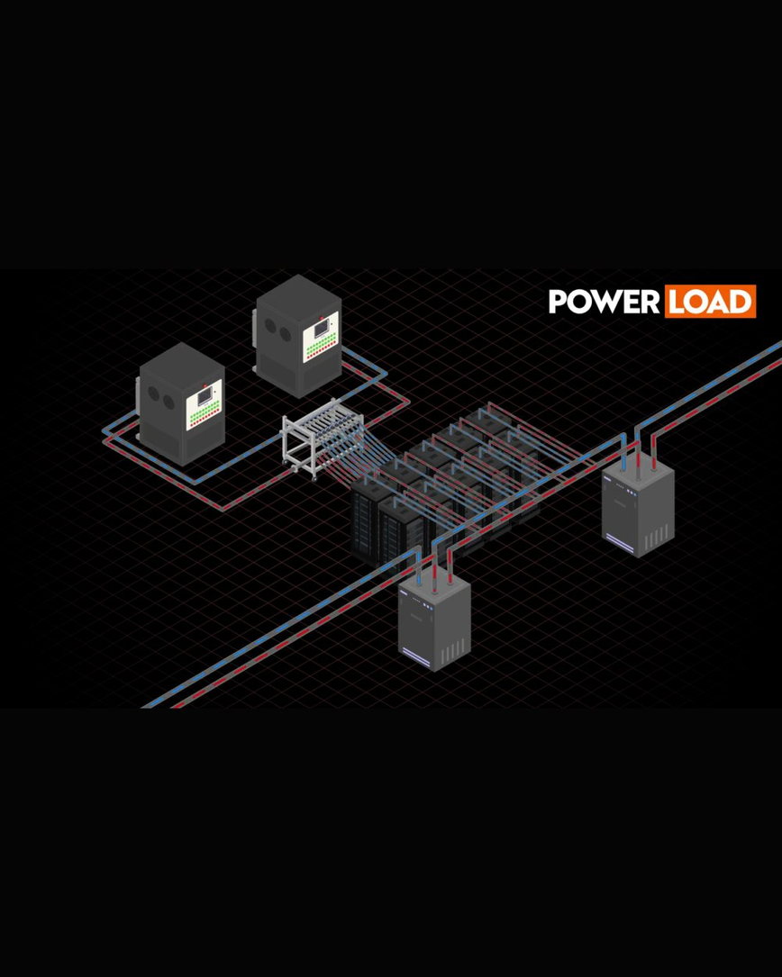
The manifold runs 1 to 2 inch hose pairs from a single secondary fluid network. One connection into the loop becomes a set of independently routed circuits.

That is what makes rack-level testing practical across a hall. Feeding each rack straight from the secondary network would mean a separate set of connections for every one, and more places for something to be inconsistent.

A flow meter on every outlet

Each outlet includes an electronic flow meter reporting live flow rate and temperature to the controller.

Because metering is per outlet rather than on the manifold as a whole, every circuit is measurable in its own right. A circuit short on flow shows up as that circuit, not as a total that does not add up.

Target pressure drop per valve

A target pressure drop can be set on each valve, which is what turns measurement into control.

Rather than balancing by eye, each circuit is given the condition it should hold and held to it. That is what makes results repeatable across a hall and across a programme.

More in this topic

Visibility inside the loop

FAQ

Answered

One connection to the secondary fluid network, fanning out into 1 to 2 inch hose pairs that are each independently metered and controlled.
Each outlet has an electronic flow meter reporting live flow rate and temperature to the controller, and a target pressure drop can be set on its valve.
Where to next

Related reading

Sizing a manifold?

Tell us how many racks you need to feed and we will spec it.